X88 expeditions - Documenting and sharing overland travels, adventures, and expeditions

December 4, 2007

Lighting - Headlamps + Auxiliary Lamps II

For night-time on road (with no oncoming traffic) and offroad driving, I decided to stick with KCHilites. The only issue was where to mount them. I decided to go with an N-Fab universal light bar, part # C995LB from Rocky Mountain Suspension Products.
I already had 3 Titanium Daylighters with 130 Watt bulbs, so I purchased an extra one for mounting on the light bar.
The picture on the right shows the KCHilite acrylic rock shield. I prefer this type of shield vs. the standard kind as it gives 100% protection against flying rocks, branches, etc. You can see how they look on the vehicle in the blue Trailblazer pictures. Of course I will also have solid white plastic covers when driving during the day so as to stay "street legal".

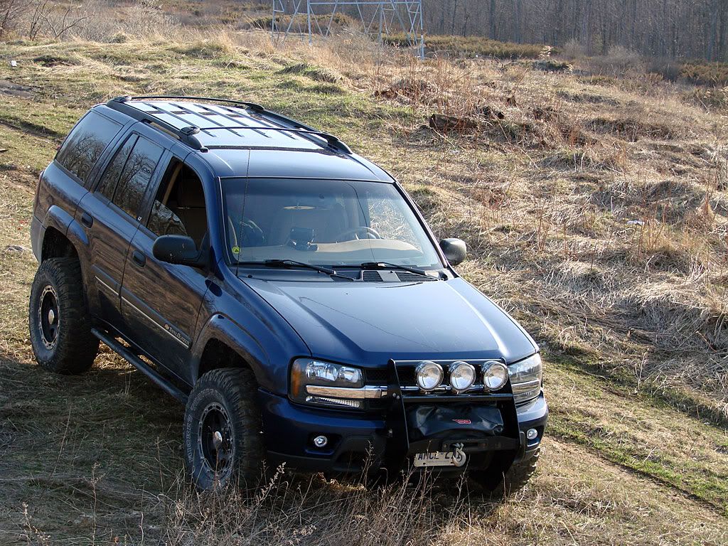
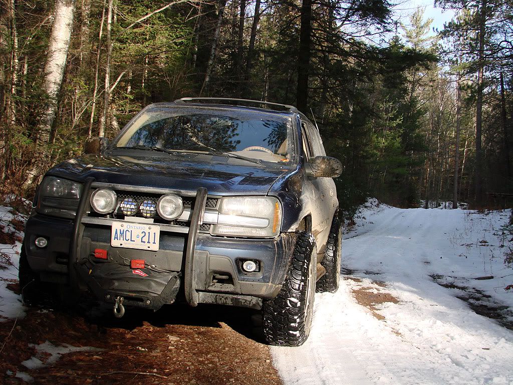
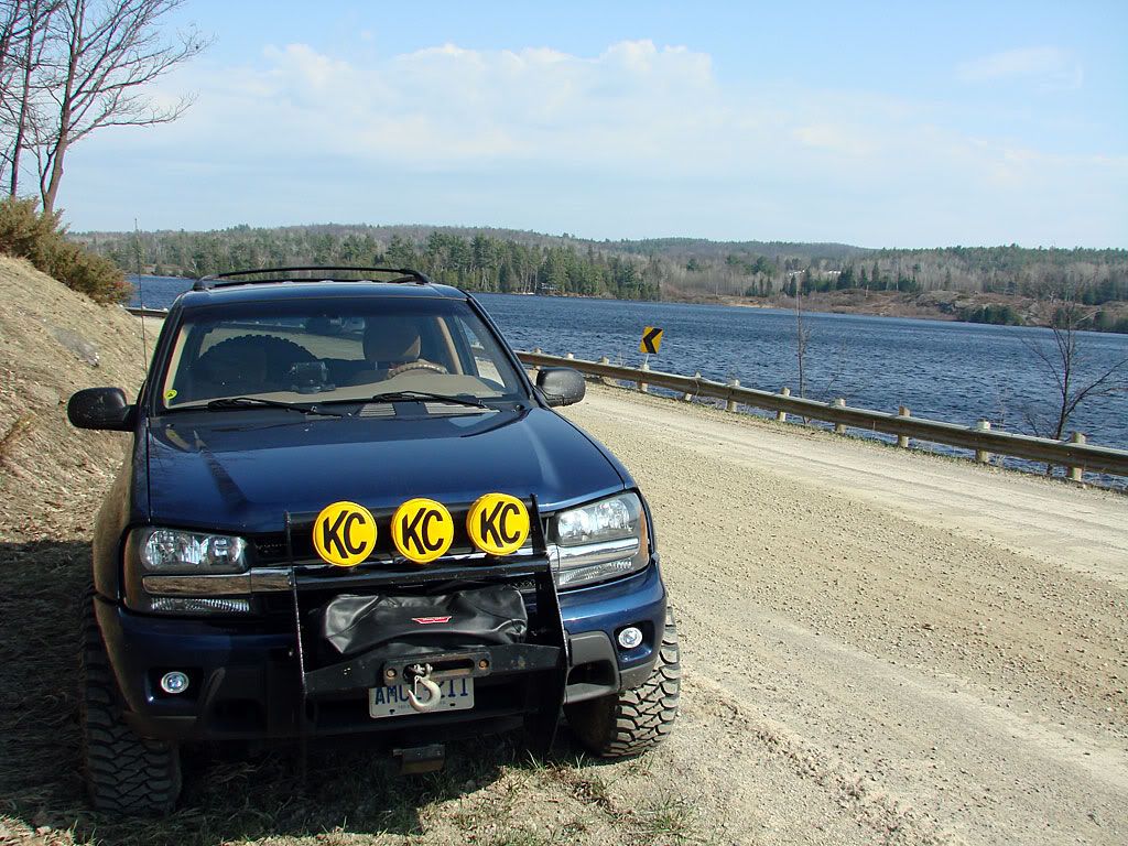
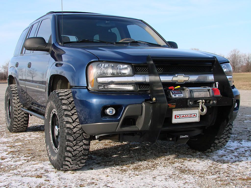
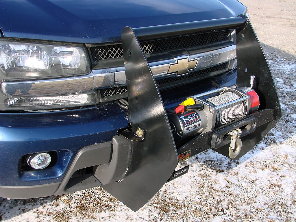
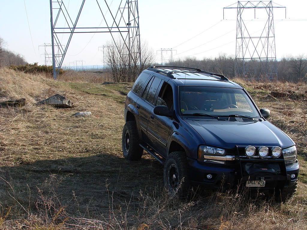
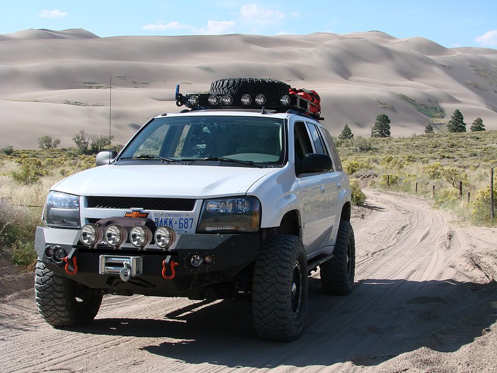
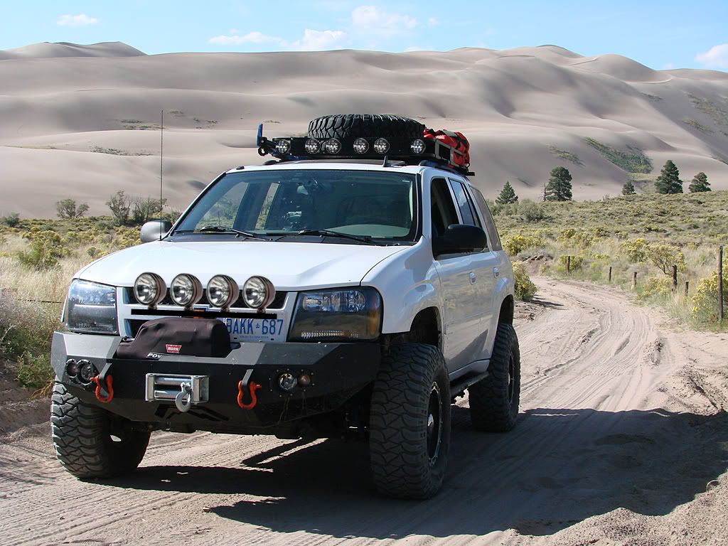
The only decision left to make is how to mount the light bar. Here are a couple of Photoshop'd images. I prefer them higher, but I just don't know if mounting the light bar to the plastic grille will be strong enough. The other option is mounting it to the offroad bumper, I don't know if I like them that low and hiding the Winch.

You may have noticed some smaller lights Photoshop'd into the front of the Surco Safari bar. For there, I have decided to go with 2 different sets of PIAA lights. On the outside, the Series 510 fog lights I have left over. And on the inside, 4 Series 510 long range lamps.
The long range lamps will augment the 130 Watt KCHilite lamps, while the fog lamps will work together with the H7 bulbs in the offroad bumper. Why the PIAA smaller (4 inch) lamps you may ask? I like the way they tuck underneath the top of the Surco Safari rack. I didn't want a massive set of full-size lights on the roof.

The wiring is definitely going to be a challenge particularly on the roof as there is no other way to permanently get power there without drilling some holes. I also want to make the fuses and relays very clean in the engine bay, perhaps some kind of extra wiring harness/box to keep everything nice and neat. More research on that is needed.

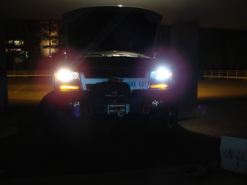
And finally the switches for all these lights. I still like wiring them into the factory switch logic, so the fog lamps (upper and lower) will be on the stock fog lamp switch and the long range lamps (upper and lower) will be on the high-beam switch. But there will be a twist:

I have bought some covered safety switches from Purple Cranium, this picture represents how I will be configuring them. When the switches are in the off position, the corresponding lights will not turn on even when they are activated with the factory switches. I.e. the safety switches must be on for the lights to work.

The left blue switch is for the lower long range set (KCHilites). The right blue switch is for the upper long range set (PIAA). And the yellow switch is for the upper fog set (PIAA). The H7 bulbs in the offroad bumper will always be available by just turning on the factory fog light switch.

Well, thats it for now. I will be posting later on the progress of this build. The next step is to mount the PIAA lamps on the Surco Safari rack. This I can do over the winter. The KCHilite mounting and all the wiring will have to wait for the Spring.

Lighting - Headlamps + Auxiliary Lamps

If you've seen pictures of my Trailblazer over the past year or two, you've probably noticed that I am somewhat of a lighting freak. I love to add auxiliary lamps if they are for actual real-world use and a benefit while driving.

This all started about 10 years ago with my Grand Prix GTP. At that time, I had a contract in Ottawa and would drive there from Toronto (4-6 hours depending on route and weather) at least twice per month. After the 10th boring trip down the 401 (you southern Ontario people know what I'm talking about) I decided to start exploring the more scenic routes to the north.

Trouble was that I would regularly go past sunset, particularly in the winter. And I didn't feel comfortable with the stock 9007 low/high beam bulbs, they just did not light up the road enough. The solution was to wedge a set of PIAA 120 Watt long range lamps into the stock fog light locations and have them activate only with the high beams. It was a big success, and after that I was hooked.

So here are some pictures of the old blue Trailblazer in 2 configurations. First a pair of PIAA P-1000XT driving lights, a pair of KCHilite 130 Watt long range lamps and a pair of PIAA 510 Series fog lamps. After installing the Mile Marker grille guard / winch carrier, I decided to add 1 more KCHilite and to temporarily jettison the fog lamps.

This set up was working very well. I wired the driving lamps to come on with the stock fog light switch, and the long range lamps to come on with the high beams.

So now with the offroad bumper, I have had to rethink the lighting a little bit.

First step was to upgrade the stock lighting. I did not want to jump into HIDs just yet so I decided on Hoen Lighting. Here is a comparison of the low-beam stock vs Hoen Titanium 9006 bulbs.
This compares the high-beam stock vs Hoen Xenonmatch Plus 9005 bulbs.
And finally, a picture of the all the Hoen bulbs installed, and the H7 bulbs in the offroad bumper replaced by Hoen Endurance Fog Lamps.

November 18, 2007

Custom Lift and Suspension - Front Setup

Front - FabTech Dirt Logic 2.5 adjustable coilovers

OK, now here's the most difficult part of the suspension build. As I mentioned in the background, I decided to go with adjustable FabTech coilovers because of 2 reasons:

  • potential droop in the front due to 200+ lbs of bumper and winch
  • potential accelerated shock wear and tear also due to the weight and the upwards mass of the 33" tires

All the way back to last year, I had this set of coilovers in mind:

These were for a 2005 Jeep ZJ. As you can see, they looked promising because of the upper mount and how it would potentially fit into our mounting cup. But more important was their bottom mounting, and how it looked like it could work with our stock strut towers (which wrap around the front CV axles).

Problem was that month upon month, I could not get any measurement data on them. Not from FabTech directly, or through my contact at North Shore Offroad. Well time was running out for my trip to Colorado so I took a BIG chance and just ordered them.

And then the worst thing that could happen, happened. I got word back from NSOR that this model was discontinued. In fact, there were never any built, other than a prototype. They decided that there was not a big enough market for them so they cancelled the program.

So I started scouring the catalog, the web site, any source I could get my hands on for a potential alternative. What jumped out at me was the FTS2500K 0"-3.5" adjustable coilover system for the Toyota Tacoma and 4Runner. The thing that sold me was the instruction manual they had online which had a very accurate technical drawing. Knowing that the width of the shock body was 2.5", I could use Photoshop and extrapolate all the other measurements.

From this I could be quite certain that the spring diameter could work, that the mounting plate could fit inside our cups, and that the length was workable. The only thing that had me worried was how to mount the bottom of the coilover to the strut tower. Well, time was still running out so I decided to just go for it!

While I was waiting for the order to come in, I used this great used parts locator and bought 2 strut assemblies locally. After removing the struts I cleaned up the towers and got them powder coated blue to match the FabTech parts. And here are all the pieces next to each other for comparison.

And some close ups on the coilovers.
As you can see, the build quality of these parts is outstanding. However, the problem I was afraid of, came to pass. The diameter of the bottom coilover mounting point was larger than the inside diameter of the strut tower. I thought about getting something fabricated that would slip inside the strut tower (and get pinched by it) and provide a pin mount that would be above the strut tower. However, this would increase the effective length of the coilover by a couple of inches. Plus I was not comfortable with changing the engineering of our suspension by making the bottom mount a swivel-type mount instead of how it is stock, i.e. firmly attached to the tower.

This is where I looked to the professionals at National4WD for help. After showing all this to Ryan at the shop, he said he had some ideas but had to talk to a person he regularly used at a machine shop and get some feedback from him. After a few days Ryan called me in and showed me the proposed solution:

  • The coilover would be inserted into the tower all the way up to the bottom of the spring cup (see picture above). This would pinch not only the spherical ball area, but also the small lip at the very top which is the full diameter of the mount.

  • To accommodate this, the inside of the tower would be machined and the inside diameter expanded.

  • The spherical ball openings would be oriented facing forward/back, to clear the bolt that partially passes through the strut mount.

  • Then for added support/safety, he would machine 2 aluminum "half-moon" inserts, joined with a bolt that actually goes through the spherical ball mount (hidden) to "fill in" the space that is part of the coilover mount design, which allows the strut tower to pinch not only at the top (where the Fabtech is round) but all the way down to the bottom of the strut mount.
So there it is. The coilover was adjusted with the bumper and winch weight to give 2.5" of lift. Anything more would probably give rise to serious CV axle binding. As I wrote in other posts, the entire vehicle has been given vigorous work outs in my mini expedition around Georgian Bay, and then on the big one to Colorado.

Again, I can't say enough about the FabTech DirtLogic shocks. Absolutely first rate. The mounting solution that Ryan came up with has been rock-solid. There does not seem to be an issue with the suspension at full extension, even though the unsprung length of the FabTech coilovers seems to be a bit longer than stock. I guess time will tell ...

Custom Lift and Suspension - Rear Setup

Rear - SkyJacker lift coils + FabTech DirtLogic 2.25 shocks

Ever since I picked up FabTech's catalog at National4WD, I was totally impressed with their products. All their stuff looks like it should be on Baja race trucks, and let me tell you, after many kms I can attest that it performs like it is.

The only problem I encountered is that since their stuff is so specialized, it ended up being really difficult to nail down a supplier. National4WD ended up not carrying the line in stock. They could get special orders, but even that proved to be problematic. Luckily North Shore Offroad in Vancouver filled in nicely, and in fact had a line to their technical department which helped out by providing some measurements on the front coilovers, but more on that later.

But first I should talk about the rear springs. As I was not going to go with the BDS suspension lift kit this time (FabTech front coilovers instead), I was not going to have the 2" spacers available from BDS.

The two options I was looking into were:
a) Spacers from another source
b) Replacement springs

I thought about trying to get the Japanese rear springs, but ultimately ended up going with something more local in the form of SkyJacker lift springs for the Tahoe/Yukon/Suburban line. SkyJacker sells 2 versions for all these models, the C25R which give 2.5" of lift and the C40R which give 6" of lift.

This decision was a bit of a chance on my part as I did not have any locally to measure. I did not know what their full outside diameter was, what was the inside diameter at the mounting points, and what their actual length was. All I had was a picture from an online source where I could see that their top and bottom ends looked similar to ours.

I went with the C25R which ultimately gave me 4" of lift in the rear. Anything more would probably result in the rear axle being moved too far forward, and potential driveshaft and u-joint angle issues. This did however result in an upward rake for the vehicle, but I personally don't mind that in this type of build.

The springs are a bit larger in outside diameter than ours, but ultimately this does not pose a problem. I was worried that they may rub against the rear of our gas tank, but they don't. They also have a greater spring rate, so you get a significantly stiffer ride. This may not be a good thing to many of you, but when you load up the rear of the TrailVoy (including the roof rack) for an expedition, it is a huge benefit. I went over many significant drops on the trails in Colorado, and the springs held up perfectly, no bottoming out, nothing. I could have probably loaded up 500 more lbs in the back without any problems.

The one thing that my fab guy did was to clamp the bottom of the spring to the spring cup. He said it was not absolutely necessary but was done for added safety.

Did I mention how awesome the FabTech DirtLogic shocks are? I think I did. I will say it again, their dampening is out of this world. I haven't experienced anything like it in all my years of driving. There is absolutely no pogo with these shocks ... none. I go over a bump, rock, anything, and there is the first compression, then ... nothing. Just outstanding.
Because of the 4" lift, I ended up going with the DirtLogic 2.25 10" travel shocks - without reservoirs. They are part number FTS81026 and have an extended length of 27.56" and a compressed length of 17.52". I have to give BDS some credit on this as I used the extended and compressed measurements they provide for the shocks they sell with their 2" lift as a guide to which FabTech ones to get. Here are some more specs:
  • 2.25” OD Steel body
  • 2.0” OD Billet Aluminum Piston
  • 7/8” Hardened Chrome Piston Rod
  • Urethane mounting ends

As you can see, their installation is a piece of cake. They basically fit in the stock mounting locations. There are a couple of points to make though:

  • They need to be mounted in the reverse direction of the stock shocks, i.e. the body at the top, piston rod at the bottom. This is because the billet body cap that holds the mounting ring is too large to fit in the bottom mount.

  • Spacers are needed at the bottom mount. Currently, I am using grade 8 washers but will be replacing them with the spacers from the JKS anti-sway bar end links, they happen to be the perfect inside diameter, and when cut in half, the perfect width.

I'll be putting in the spacers soon, along with some FabTech boots I bought to protect the piston rods from stones, winter, etc.

Overall, I am ecstatic with the rear set up. It performed flawlessly on those mountain and canyon trails in Colorado.

November 17, 2007

Custom Lift and Suspension - Body Lift and Sway Bar

BDS 2" body lift

I decided to go with the BDS Suspension body lift again as I like the way it helps with my 33" tires. Trimming is still required to the wheel well lining, and to one section of metal (see my old 33" tire thread), but with the body lift, you can usually stay away from trimming the actual fender, as The Roadie and JamesDub did, great work by the way.

With the lift at 2", the frame rails are not extremely exposed. And with the custom rock sliders I have, you can barely notice the rails.

Hotchkis rear anti-sway bar and poly bushings + front poly busings

I ended up going with the Hotchkis upgrade again, although I first tried the Eibach front and back anti-sway bar kit. Be careful on that Eibach kit as they claim it is for ALL years, however, the front does not fit the latest years when the front bar mounting locations were changed and the bar reduced in size. Luckily the dealer I bought it from took it back.

The Hotchkis kit comes with a thicker rear bar and poly bushings. Plus they give you two sets of front poly bushings, one set for the older larger diameter front bar, and one set for the newer smaller bar.

Custom Lift and Suspension - Disconnects

After my blue 2002 Trailblazer was picked up by the insurance company (total write-off), I began searching for a new Trailblazer, as I had decided that I had too much knowledge (and some parts that I pulled from the 2002) invested to start fresh with another vehicle. This feeling was multiplied as I still wanted to make my expedition from Toronto to Colorado at the end of August.

So I renewed my efforts to research a custom suspension setup. Additionally, this was made absolutely necessary in my opinion as I had also decided to go with a custom-adapted front bumper setup and new Warn winch, all of which would add over 200 lbs to the front of my vehicle.

After all my research, here is what I have finalized on:

  • BDS 2" body lift
  • Front - FabTech Dirt Logic 2.5 adjustable coilovers
  • Rear - SkyJacker lift coils + FabTech DirtLogic 2.25 shocks
  • Hotchkis rear anti-sway bar and poly bushings + front poly bushings
  • JKS front and rear anti-sway bar links that disconnect

Lets get the easier stuff out of the way first.

JKS front and rear anti-sway bar links that disconnect

Why go with disconnectable links when our stock articulation is not great to begin with, specifically the front? Well it was not all about being able to disconnect.

My main requirement was to upgrade the end links to longer heavy-duty units that would not need replacing ... ever. These units from JKS Manufacturing more than fit the bill. As you can see, they are extremely heavy duty, are adjustable, have poly bushings, are greasable, and ultimately can be removed and rebuilt by replacing the bushings.

The two model numbers that I guessed would best suit my application were 3100 (shorter for front) and 3104 (longer for rear). I ended up not having to use the spacers, but will actually use the spacers in another area, just turned out lucky in that respect.

The mounting ended up being straight-forward in the front, but not in the rear. The angles of the frame mounting points and anti-sway bar holes in the front allow for the 3100 to be mounted with no modifications to anything. The rear is a different story because of 2 factors.

  1. The frame mounting point and hole is on a strange angle, and no matter what, when the mounting post is attached, it is on too much of an angle vertically to allow the link to be slipped on - the bushing just does not rotate enough.
  2. The brake line is right in the way at the frame mounting location. Even though the link could be slipped onto the post (if it were at the correct angle), each time that was done the brake line would have to be moved out of the way, and too much of that could definitely cause problems down the road.

So what my fab guy did was to bolt and weld an extension off of the mounting point and frame. This brings the mounting point down and allows for the post to be attached at a perfect angle and as a result, the 3104 ends up being perfectly vertical.

Here are a couple of pictures of the front and rear:

So far, the links have been rock-solid, and I have put a lot of kms on them. The next test is this winter here in southern Ontario with our snow, sand, and salt. What their condition will be in the spring is yet to be seen. I may end up replacing the bushings which is not a big deal ($3.50 each), plus I will probably touch up the actual links in a week or two with some POR-15 as they have incurred some scratches. The mounting posts are stainless steel and I have used grade 8 mounting bolts so rust on these should not be an issue.

Custom Lift and Suspension - Background

For the past year and a half, I have been researching and planning to put together a custom suspension for my Trailblazer, one that addresses several issues I had encountered since starting to upgrade my vehicle. But first, some background.

Through several iterations, I had modified my blue 2002 Trailblazer to the point where I was almost fully happy with the build. It had the following installed at the time of my tree accident:

  • BDS suspension lift
  • BDS body lift
  • Bilstein HD shocks
  • Custom rock sliders from National4WD
  • Curt front hitch receiver
  • MileMarker grille guard and winch mount
  • T-Max 9000 winch

Here are some pictures:

However, after all this was installed, I started to notice some problems. Mainly it was the accelerated deterioration of the Bilstein shocks, specifically the front ones. I believe that all the additional weight I had in the front, including the 33" tires (which put strain on the shocks going upwards) was too much in the long term for even the heavy duty Bilsteins.

The other inherent problem with this setup was the reduction of front approach angle both from the MileMarker and the Curt. I left the Curt on the vehicle (which bolts to the frame) as a strong winch/tow point.

So, even though I was pretty much settled on the front guard/winch setup (notwithstanding the approach angle issue), I started looking for alternatives to solve the shock problem, which unfortunately is made more difficult as the front suspension is a coilover setup.

November 12, 2007

Going For The 4•5•6 - Rock Guard Spider

Long time since my last post on this topic. Unfortunately the rear axle is still where I left it, sitting in my friend's backyard, with no work done on it. Well its getting colder up here and we had our first snowstorm about 100 km north of Toronto a few days ago. It didn't stick around, but I know its going to come sooner or later. So I am going to talk to my fabrication guy at National4WD and see if they will keep it in their shop till spring. I hope to put some new gears (4.56) and a locker (Auburn Ected) in there for the new year, maybe in February.

I also have decided to see if I can find a similar deal on a front axle housing locally. It would be easier to get the front and rear axles all done up with new gears and oil before leaving the Trailblazer in the shop.

But on to the new great news.

Purple Cranium have started production on a half spider for our rear ends, both the 8 inch and 8.6 inch. I sent them the covers for both and they went to work. Here's my brand new, orange powder coated, rock guard:

As you can see, they built it so that it clears the deeper 8.6 cover. I was going to wait and put it on only after I swapped rear axles, however, as I am going in for a fluid check and service on the axles and transfer case before winter, I will get them to put it on. Pictures of that later.

November 4, 2007

Rear Spare Tire Carrier - Pictures

Here are some pics I took late this afternoon. The first one is a close-up of the clamp. You can see how the very thick piece of metal is shaped (like a J) and how the U-bolt is tight against the Surco going into the hitch receiver. The other three pictures are of the various states of open hatches and lowered spare carrier.
I also bought a license plate relocation adapter (with light) and mounted it to the side of the spare. However, it does not move the plate enough to the left so the right side of it, with the year sticker, is not visible. I'm going cut the llight part off and use it to hold the plate inside the spare tire, where it used to be. That way I can be 100% legal - visible and lit.

Rear Spare Tire Carrier - Fabrication

The first order of business was to cut the part of the spare tire mount that slides into the hitch receiver (red line):
Next was to measure and drill two holes up from the red line, this is where the center bolt of the Surco fold up adapter would go through. The holes have to be big enought to fit the stainless steel sleeve that comes with the Surco. This sleeve is what allows it to pivot nicely. Here's a couple of pictures of it just before drilling the holes:
The next three modifications would depend on the user and what kind of rims/tires they have (I have the 33x11.5 Baja MTZs)
  • I drilled 2 holes into the part that slides into the hitch receiver to adjust how far out the whole assembly sits. The tire needs to be out far enough to clear the rear wiper. As luck would have it, the tire sits low enough so that I can open the top window and access the rear without lowering the Curt. This is OK to grab lighter things from the back, but for anything heavier such as coolers, or large suitcases, the spare needs to be lowered.

  • I had 2 pieces of 1/4" thick 2" wide square tube cut and bolted them to the face plate of the Curt. This was needed to push the wheel outwards and allow the tire to clear the back of the Surco assembly. I used grade 8 bolts for this and ultimately had them welded on as well so that I do not need to fumble with the bolts when putting the wheel on and taking it off.

  • And finally, I had to cut about 1/2 an inch off the metal tab that sticks out at the back of the Surco. The tire was not completely clearing this when I would raise and lower the Curt.

All exposed metal was sprayed with black anti-rust paint. So far I have not had to grease anything but that is yet to be seen this winter. I think I will try some graphite lubricant spray first and see how that goes. I have used it before in hitch locks and it works great. Speaking of hitch locks, I ended up using two: - one at the actual hitch receiver - and one to replace the pin that holds the Curt upright (didn't want some yahoo in a parking lot pulling it to see what would happen) In discussions with The Roadie, he warned me about the Curt rattling inside the hitch receiver, and that all products he tried did not do anything (except for his TireGate which has a real solid system to clamp it). I ended up trying the clamp from FastTrackRacks (see picture above) as I was purchasing the Surco from them as well. Note: the clamp I got looks a little different from their picture. The clamp uses a U-Bolt that is almost exactly 2 inches inside width so fits very snugly over the hitch receiver. The metal piece then gets tightened up against the hitch reciever on one side and the Surco on the other. This is a very good product and locks everything into place extremely well. I have had absolutely no rattling since it was installed. Very happy with this product. So here are some pictures of the whole assembly in action. Unfortunately I don't have any with the rear window open or the spare down and the hatch up. But I will try to take some this afternoon and post them later.

So far I am very happy with what I put together and it worked well on the expedition. The spare is a bit heavy to lower and raise, but workable. Plus when I camped out for the one night on the other side of Medano Pass, it was handy to leave the spare lowered and use it as a makeshift table.